
What is a dieline? Cut, crease and bleed explained
A cutting die is production tooling; a dieline file describes the flat board outline and folds. MakePk exports separate cut, crease and bleed layers. A converter may require additional process marks.
Cut: what actually gets cut
Outer outlines and windows are usually closed cut paths. Tongue roots and reliefs can intentionally use open knife strokes. An open path is not automatically an error: compare it with the construction and converter specification.
Crease: where the board folds
Creases guide the fold without cutting through the board. Cut and crease marks are not interchangeable. Score depth, width and direction depend on the board and equipment.
Bleed: the printer’s margin
Bleed extends artwork beyond the trim boundary to reduce exposed unprinted edges after cutting variation. The illustrated 3 mm is an example; confirm the actual allowance with the print and finishing workflow. Bleed is not a cut or crease operation.
Construction diagram
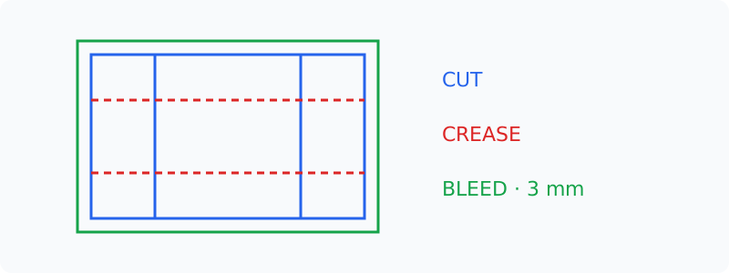
Download diagram SVG (not a production dieline)
| Item | What to check |
|---|---|
| Cut | Cut boundaries and holes |
| Crease | Fold locations, not through-cuts |
| Bleed | Artwork extension, not a cutting path |
Worked examples and tool checks
Check in the tool — L=60, W=90, H=150, T=0.5 mm
Die face: 61 × 91 × 150 mm. Outer: 61 × 91 × 151 mm.
Practical decisions and common mistakes
Separate structure from artwork before designing a print layout. Mark which panel faces out, where the package folds and which areas need glue on a blank sample. A logo centred on the flat sheet is not necessarily centred on the assembled front. Small type crossing a fold can be hard to align after cutting. Confirm panel orientation with simple marks before committing to finished artwork.
Checks before handing off a file
Hide the artwork layer and inspect cut, crease and bleed information separately in the exported file. Duplicate paths can cause repeated passes in some fabrication workflows; a missing slot can prevent a lock working. However, intentional open cuts exist at some tuck roots. Do not automatically join every endpoint: preserve the structural intent and confirm technical-line handling with the maker.
Export and sample checks
Open exported SVG, PDF or DXF in millimetres at 100% scale. Measure a known panel and inspect CUT/CREASE/BLEED separately. Cut an unprinted sample and check the product, inserts, tongues and lid before converter review. Diagrams explain the model; they do not include machine kerf, springback or supplier compensation.
Frequently asked questions
- Must every cutting path be closed?
- Outer boundaries and enclosed holes generally close, but intentional open cuts can occur at tuck roots. Check structural purpose rather than automatically joining endpoints.
- Is bleed always 3 mm?
- No. It is a common example and a setting in selected tools. Confirm the actual allowance with the printer and cutting workflow.
- Are the legend colours an international standard?
- No. They are MakePk preview conventions. Identify operation types and layers because another application or maker may use different colours.
- How do I check printed scale?
- Choose Actual size or 100%, disable Fit to page and measure a known edge. If the layout exceeds the printable area, use suitable paper or tiled printing.
- Do I need a blank sample before production?
- Use the intended material to check dimensions, folds, clearance and actual contents, then confirm processing with the maker. A screen preview cannot replace a physical test.
Try it on the tuck carton page